“Say something positive, and you’ll see something positive.”
Resistance:
The property of a substance which opposes the flow of electric current (or electricity) through it is called Resistance OR Resistance is the ability of a circuit which opposes current. Mica, Glass, Rubber, Wood etc. are the examples of resistive materials. The unit of resistance is OHM (Ω) where 1Ω = 1V/1A. which is derived from the basic electrical Ohm’s law = V = IR.
Other definitions of Ohm “Ω “are as follows; If there is a potential difference of 1 volt between two ends of the conductor and the flowing current through it is 1Ampere, then the resistance of that conductor would be 1 Ohm (Ω). OR If 1 ampere of current is flowing through a resistance, and 1 joule per second (1Watt) energy (in the form of heat) is generated, then the measurement of that resistance is 1 Ω.
Ohm is the measurement quantity of resistance, which produces one joule of energy (in the form of heat) in one second, when one ampere of current is flowing through it. The reciprocal of the resistance is called conductance.
Resistor
A resistor is a component or device designed to have a know value of resistance. OR,
Those components and devices which are specially designed to have a certain amount of resistance and used to oppose or limit the electric current are called resistors.
Good to know: Resistance of a resistor depends on their length (l), resistivity (ρ) and its cross sectional area (a) which is also known as laws of resistance … R = ρ (l/a) .
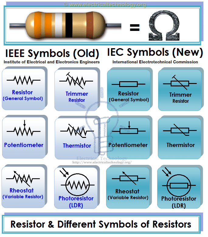
Symbols of Different Types of Resistors. IEEE & IEC symbols of Resistors
Resistors and Symbols of Different Types of Resistors. IEEE & IEC symbols of Resistors
Types of Resistors
Resistors are available in different size, Shapes and materials. We will discuss all possible resistor types one by one in detail with pro and cons and application/uses.
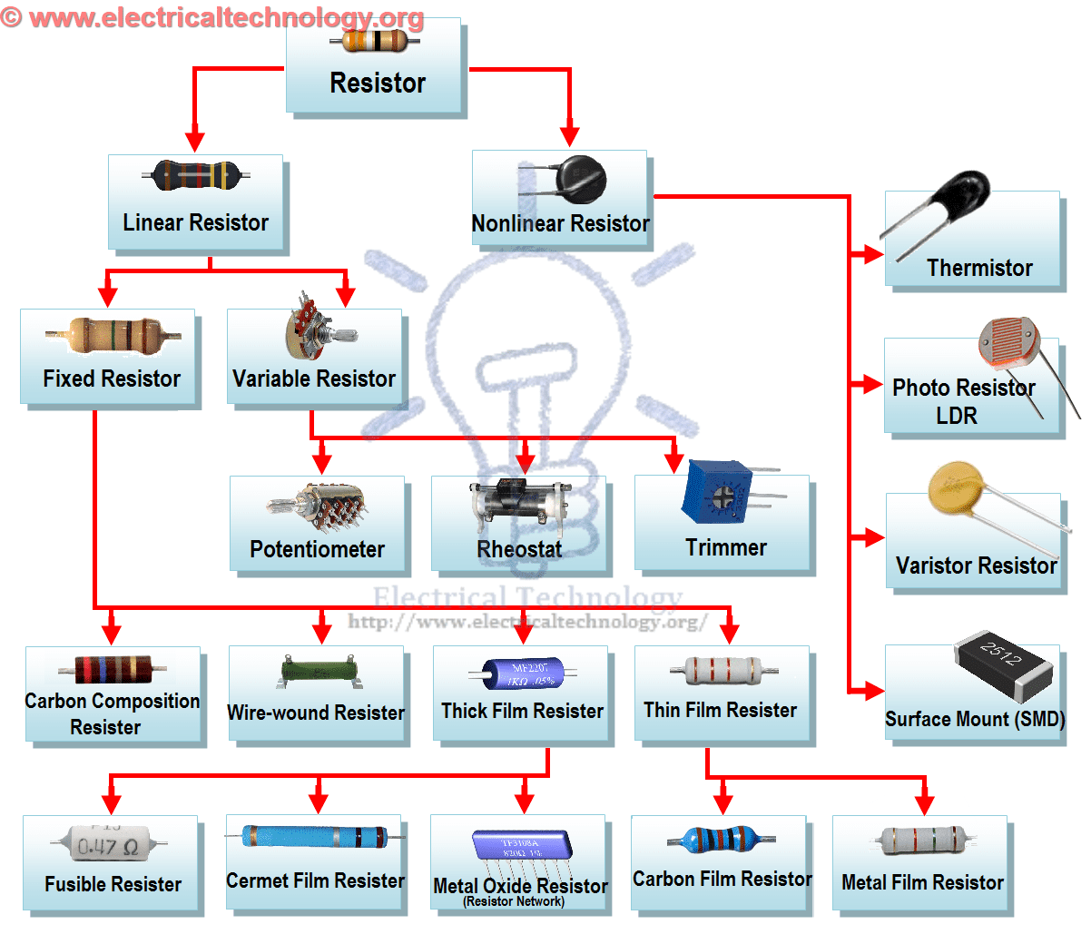
Different Types of Resistor Chart/Tree.
There are two basic types of resistors.
Linear Resistors
Non Linear Resistors
1. Linear Resistors:
Those resistors, which values change with the applied voltage and temperature, are called linear resistors. In other words, a resistor, which current value is directly proportional to the applied voltage is known as linear resistors.
Generally, there are two types of resistors which have linear properties.
1. 1. Fixed Resistors 1. 2. Variable Resistors
1. 1. Fixed Resistors
As the name tells everything, fixed resistor is a resistor which has a specific value and we can’t change the value of fixed resistors.
Types of Fixed resistors.
Carbon Composition Resistors
Wire Wound Resistors
Thin Film Resistors
Thick Film Resistors
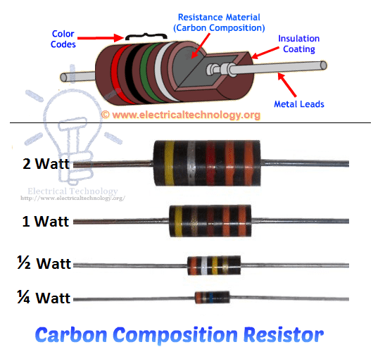
1. 1. 1) Carbon Composition Resistors
A typical fixed resistor is made from the mixture of granulated or powdered carbon or graphite, insulation filler, or a resin binder. The ratio of the insulation material determines the actual resistance of the resistor. The insulating powder (binder) made in the shape of rods and there are two metal caps on the both ends of the rod.
There are two conductor wires on the both ends of the resistor for easy connectivity in the circuit via soldering. A plastic coat covers the rods with different color codes (printed) which denote the resistance value. They are available in 1 ohm to 25 mega ohms and in power rating from ¼ watt to up to 5 Watts. Carbon Composition Resistors.Construction and Wattage Rating
Characteristic of Fixed Resistors Generally, they are very cheap and small in size, hence, occupy less space. They are reliable and available in different ohmic and power ratings. Also, fixed resistor can be easily connected to the circuit and withstand for more voltage.
In other hand, they are less stable means their temperature coefficient is very high. Also, they make a slight noise as compared to other types of resistors.
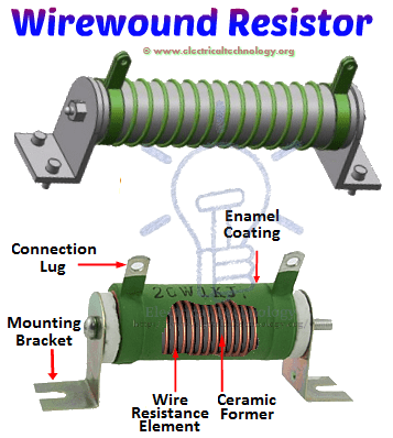
1. 1. 2) Wire wound Resistors
Wire wound resistor is made from the insulating core or rod by wrapping around a resistive wire. The resistance wire is generally Tungsten, manganin, Nichrome or nickel or nickel chromium alloy and the insulating core is made of porcelain, Bakelite, press bond paper or ceramic clay material.
The manganin wire wound resistors are very costly and used with the sensitive test equipments e.g. Wheatstone bridge, etc. They are available in the range of 2 watts up to 100 watt power rating or more. The ohmic value of these types of resistors is 1 ohm up to 200k ohms or more and can be operated safely up to 350°C.
in addition, the power rating of a high power wire wound resistor is 500 Watts and the available resistance value of these resistors are is 0.1 ohm – 100k Ohms. Construction of Wire wound Resistors
Advantages and Disadvantage of Wire wound Resistors Wire wound resistors make lower noise than carbon composition resistors. Their performance is well in overload conditions. They are reliable and flexible and can be used with DC and Audio frequency range. Disadvantage of wire wound resistor is that they are costly and can’t be used in high frequency equipments.
Application/Uses of Wire Wound Resistors Wire wound resistors used where high sensitivity, accurate measurement and balanced current control is required, e.g. as a shunt with ampere meter. Moreover, Wire wound resistors are generally used in high power rating devices and equipments, Testing and measuring devices, industries, and control equipments.
1. 1. 3) Thin Film Resistors
Basically, all thin film resistors are made of from high grid ceramic rod and a resistive material. A very thin conducting material layer overlaid on insulating rod, plate or tube which is made from high quality ceramic material or glass. There are two further types of thin film resistors.
1. Carbon Film Resistors 2. Metal Film Resistors
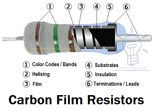
1. 1. 3. 1) Carbon Film Resistors
Carbon Film resistors contains on an insulating material rod or core made of high grade ceramic material which is called the substrate. A very thin resistive carbon layer or film overlaid around the rod. These kinds of resistors are widely used in electronic circuits because of negligible noise and wide operating range and the stability as compared to solid carbon resistors. Construction of Carbon Film Resistors & Its labels.
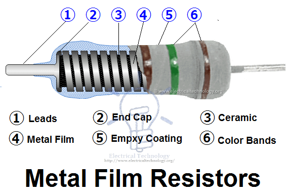
1. 1. 3. 2) Metal Film Resistors
Metal film resistors are same in construction like Carbon film resistors, but the main difference is that there is metal (or a mixture of the metal oxides, Nickel Chromium or mixture of metals and glass which is called metal glaze which is used as resistive film) instead of carbon. Metal film resistors are very tiny, cheap and reliable in operation. Their temperature coefficient is very low (±2 ppm/°C) and used where stability and low noise level is important. Metal Film Resistor. Construction and name of internal parts.
1.1.4) Thick Film Resistors
The production method of Thick film resistors is same like thin film resistors, but the difference is that there is a thick film instead of a thin film or layer of resistive material around. That’s why it is called Thick film resistors. There are two additional types of thick film resistors.
1. Metal Oxide Resistors 2. Cermet Film Resistors 3. Fusible Resistors
1.1.4.1) Metal Oxide Resistors
By oxidizing a thick film of Tin Chloride on a heated glass rod (substrate) is the simple method to make a Metal oxide Resistor. These resistors are available in a wide range of resistance with high temperature stability. In addition, the level of operating noise is very low and can be used at high voltages.
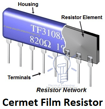
1.1.4.2) Cermet Oxide Resistors
In the cermet oxide resistors, the internal area contains on ceramic insulation materials. And then a carbon or metal alloy film or layer wrapped around the resistor and then fix it in a ceramic metal (which is known as Cermet). They are made in the square or rectangular shape and leads and pins are under the resistors for easy installation in printed circuit boards. They provide a stable operation in high temperature because their values do not change with change in temperature. Cermet Film Resistor Network Construction
1.1.4.3) Fusible Resistors
These kinds of resistors are same like a wire wound resistor. When a circuit power rating increased than the specified value, then this resistor is fused, i.e. it breaks or open the circuit. That’s why it is called Fusible resistors. Fusible restores perform double jobs means they limit the current as well as it can be used as a fuse.
They used widely in TV Sets, Amplifiers, and other expensive electronic circuits. Generally, the ohmic value of fusible resistors is less than 10 Ohms.
1. 2) Variable Resistors
As the name indicates, those resistors which values can be changed through a dial, knob, and screw or manually by a proper method. In these types of resistors, there is a sliding arm, which is connected to the shaft and the value of resistance can be changed by rotating the arm. They are used in the radio receiver for volume control and tone control resistance.
Following are the further types of Variable Resistors
1. Potentiometers 2. Rheostats 3. Trimmers
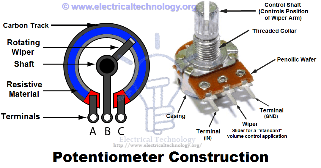
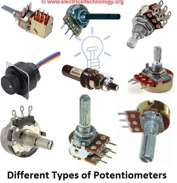
1.2.1) Potentiometers
Potentiometer is a three terminal device which is used for controlling the level of voltage in the circuit. The resistance between two external terminals is constant while the third terminal is connected with moving contact (Wiper) which is variable. The value of resistance can be changed by rotating the wiper which is connected to the control shaft. Potentiometer Construction
This way, Potentiometers can be used as a voltage divider and these resistors are called variable composition resistors. They are available up to 10 Mega Ohms. Different Types of Potentiometers
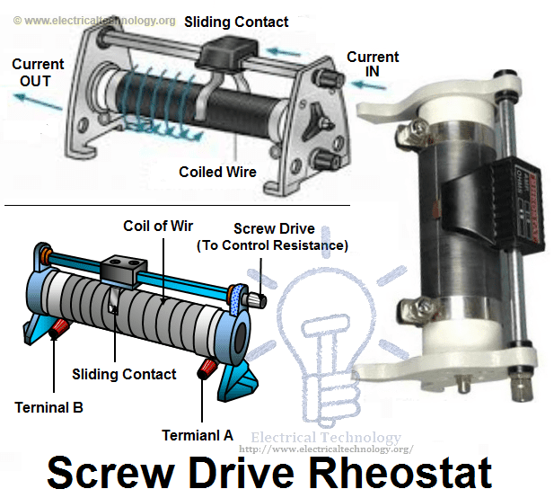
1.2.2) Rheostats
Rheostats are a two or three terminal device which is used for the current limiting purpose by hand or manual operation. Rheostats are also known as tapped resistors or variable wire wound resistors. Types of Rheostats resistor and construction of Screw Drive Rheostat
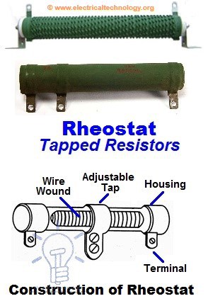
To make a rheostats, they wire wind the Nichrome resistance around a ceramic core and then assembled in a protective shell. A metal band is wrapped around the resistor element and it can be used as a Potentiometer or Rheostats (See the below note for difference between Rheostat and Potentiometer). Construction of Tapped Rheostat
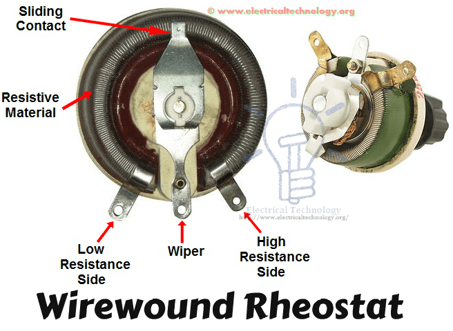
Variable wire wound resistors are available in the range of 1 ohm up to 150 Ohms. The available power rating of these resistors is 3 to 200 Watts. While the most used Rheostats according to power rating is between 5 to 50 Watts. Wirewound Rheostat Construction
Good to Know:
What is the main Difference between Potentiometer and Rheostats?
Basically, there is no difference between Potentiometer and Rheostat. Both are variable resistors. The main difference is the use and circuit operation, i.e. for which purpose we use that variable resistor?
For example, if we connect a circuit between resistor element terminals (where one terminal is a general end of the resistor element while the other one is sliding contact or wiper) as a variable resistor for controlling the circuit current, then it is Rheostats.
In the other hand, if we do the same as mentioned above for controlling the level of voltage, then this variable resistor would be called a potentiometer. That’s it.
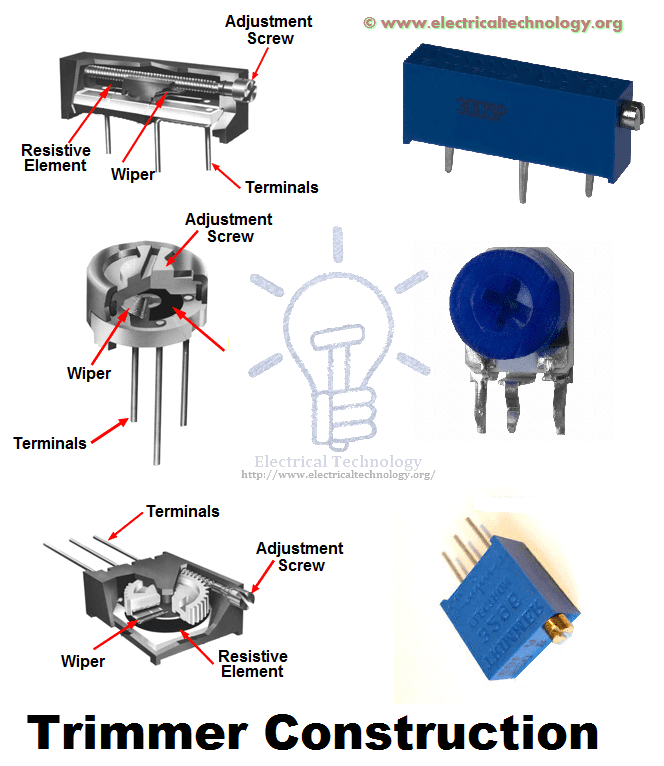
1.2.3) Trimmers
There is an additional screw with Potentiometer or variable resistors for better efficiency and operation and they are known as Trimmers. The value of resistance can be changed by changing the position of screw to rotate by a small screwdriver. Construction of Different Types of Trimmers. Trimmer potentiometer Resistor construction
They are made from carbon composition, carbon film, cermet and wire materials and available in the range of 50 Ohms up to 5 mega ohms. The power rating of Trimmers potentiometers are from 1/3 to ¾ Watts.
2. Non Linear Resistors
We know that, nonlinear resistors are those resistors, where the current flowing through it does not change according to Ohm’s Law but, changes with change in temperature or applied voltage.
In addition, if the flowing current through a resistor changes with change in body temperature, then these kinds of resistors are called Thermisters. If the flowing current through a resistor change with the applied voltages, then it is called a Varistors or VDR (Voltage Dependent Resistors).
Following are the additional types of Non Linear Resistors.
1. Thermisters 2. Varisters (VDR) 3. Photo Resistor or Photo Conductive Cell or LDR
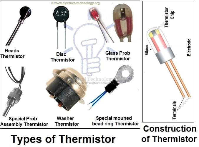
2.1) Thermisters
Thermisters is a two terminal device which is very sensitive to temperature. In other words, Thermisters is a type of variable resistor which notices the change in temperature. Thermisters are made from the cobalt, Nickel, Strontium and the metal oxides of Manganese. The Resistance of a Thermister is inversely proportional to the temperature, i.e. resistance increases when temperature decrease and vice versa. Types of Thermisters & Its Construction
It means, Thermisteres has a negative temperature coefficient (NTC) but there is also a PTC (Positive Temperature Coefficient) which a made from pid barium titanate semiconductor materials and their resistance increases when increases in temperature.
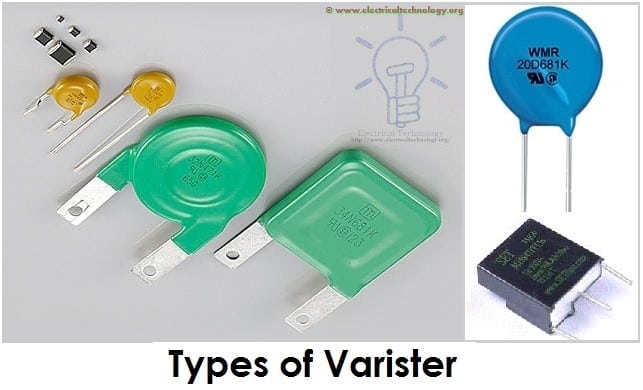
2.2) Varisters (VDR)
Varisters are voltage dependent Resistors (VDR) which is used to eliminate the high voltage transients. In other words, a special type of variable resistors used to protect circuits from destructive voltage spikes is called varisters. When voltage increases (due to lighting or line faults) across a connected sensitive device or system, then it reduces the level of voltage to a secure level i.e. it changes the level of voltages. Types of Varisters
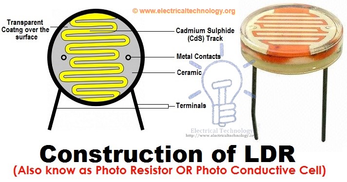
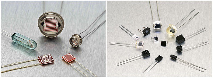
2.3) Photo Resistor or Photo Conductive Cell or LDR (Light Dependent Resistors)
Photo Resistor or LDR (Light Dependent Resistors) is a resistor which terminal value of resistance changes with light intensity. In other words, those resistors, which resistance values changes with the falling light on their surface is called Photo Resistor or Photo Conductive Cell or LDR (Light Dependent Resistor). The material which is used to make these kinds of resistors is called photo conductors, e.g. cadmium sulfide, lead sulfide etc. Construction of LDR (Light Dependent Resistor), Photo-resistor or photo conductive cell
When light falls on the photoconductive cells (LDR or Photo resistor), then there is an increase in the free carriers (electron hole pairs) due to light energy, which reduce the resistance of semiconductor material (i.e. the quantity of light energy is inversely proportional to the semiconductor material). It means photo resistors have a negative temperature coefficient. Types of Photo cells, and LDR
Application and Uses of Photo Resistors/Photo Conductive Cells or LDR
These types of resistors are used in burglar alarm, Door Openers, Flame detectors, Smock detectors, light meters, light activated relay control circuits, industrial, and commercial automatic street light control and photographic devices and equipments.
Uses / Application of Resistors
Practically, both types of resistors (Fixed and Variable) are generally used for the following purposes. Resistors are used: I. For Current control and limiting II. To change electrical energy in the form of heat energy III. As a shunt in Ampere meters IV. As a multiplier in a Voltmeter V. To control temperature VI. To control voltage or Drop VII. For protection purposes, e.g. Fusible Resistors VIII. In laboratories IX. In home electrical appliances like heater, iron, immersion rod etc. X. Widely used in the electronics industries
Clap Switch Circuit Electronic Project Using 555 Timer & BC 547 Transistors
Introduction
Clap Switch is a basic Electronics mini-project, made with the help of the basic components. Clap Switch has the ability to turn ON/OFF any electrical component or circuit by the clap sound.
It is known as Clap Switch, because the condenser mic which will be used in this Project will have an ability to take the sound having same pitch as the Clap sound as the input. Although it doesn’t mean that the sound will have to be of Clap sound, it can be any sound having the same high pitch as of Clap. We can also say that it converts the Sound energy into the Electrical Energy, because we are giving an input to the circuit as a sound whereas the Circuit gives us the output as a LED glow (Electrical Energy).
As already mentioned, this project is basic Electronics mini-project, so this project is made of the basic components. Following is the list of the components required to make the Clap Switch.
1K, 4.7K, 47K, 330 and 470 ohm resistors
10µF and 2 100nF capacitors
Electric Condenser mic
Two BC547 transistors
LED
555 timer
9V Battery
Working Principle of Clap Switch Circuit
This circuit (As shown below) is made with the help of Sound activated sensor, which senses the sound of Clap as input and processes it to the circuit in order to give the Output. When sound is given as the input to the Electric Condenser Mic, it is changed into the Electrical Energy as the LED turns on. LED turns ON, as we give sound input and it turns OFF automatically after few seconds. Turn-On LED timer can be changed by varying the value of 100mF capacitor as it is connected with 555 timer whose main purpose is to generate the pulse.
Although the name of the circuit is the Clap Switch, but you are not restricted to give input as the Clap only. It can be any sound, having same pitch as of Clap so this can also be called as “Sound Operated Switch”. This circuit is mainly based on transistors, because the negative terminal of Mic is directly connected with the transistor. In this circuit, we haven’t used any Electronic Switch to turn on/off the circuit, so when you are connecting the battery with the circuit, it means your circuit is now turned ON and it will take the inputs in the form of Sound Energy. You can modify this circuit by using Relay as Electronic Switch to turn the circuit ON or OFF.
As soon as we give the sound input to the circuit, it amplifies the sound signals and proceeds them to the 555 timers which generates the pulse to the LED, making it turn ON. You are to make sure, that the negative side of the Condenser mic is connected with the amplifier or the circuit will heat-up and may not working with different models of transistors etc. You cannot increase the sensitivity of the Condenser mic for long usage, it has short range by default. It is also applicable for the LAMP, so this circuit has many opportunities for modification.
Clap Switch Circuit Diagram
Advantages & Disadvantages
It can used to turn ON and OFF the LED or LAMP simply, by clapping your hands.
We can also remove LEDs and place a FAN or any other electric component on the output in order to get desired result.
The Condenser Mic used in this circuit has the short range as a default, which cannot be varied.
Applications
Clap Switch is not restricted to turn the LEDs ON and OFF, but it can be used in any electric appliances such as Tube Light, Fan, Radio or any other basic circuit which you want to turn ON by a Sound.


 Clap Switch Circuit Electronic Project Using 555 Timer & BC-547 Transistors
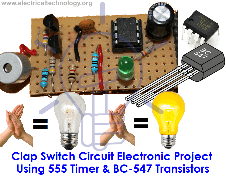

 Clap Switch Circuit Diagram


