HIREN BOOT CREAT BOOTABLE IN USB
Download and Run USB Disk Storage Format  USBFhttp://www.hiren.info/download/freeware-tools/USBFormat.zipormat.zip (34KB)

Step 3
Download grubinst_gui grub4dos.zip (179KB) and Run as Administrator

Download grubinst_gui

Step 4
Insert the BootCD (10.3 or newer) in the CD Drive and Copy everything from CD to USB Flash Drive
Insert the BootCD (10.3 or newer) in the CD Drive and Copy everything from CD to USB Flash Drive
Step 5
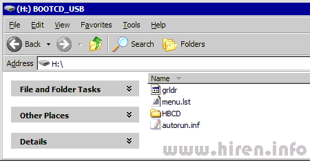
Copy grldr and menu.lst from grub4dos.zip (or from HBCD folder) to the usb drive

Copy grldr and menu.lst from grub4dos.zip (or from HBCD folder) to the usb drive

Step 6
Test Your USB Drive (read bottom of the page for troubleshoot)
Test Your USB Drive (read bottom of the page for troubleshoot)
Make sure you set your computer to boot from USB Flash Drive
To Enter the BIOS press the "Del" button on your keyboard. Alternatives are "F1", "F2", "Insert", and "F10". Some PC's BIOS might even require a different key to be pressed. Commonly a PC will show a message like "Press [Del] to enter Setup" to indicate that you need to press the "Del" key. Some AMI BIOS require you to enable the option "USB Keyboard Legacy support"!
For AMI BIOS:
- Go to "Feature Setup". "Enable" these options: "USB Function Support",
"USB Function For DOS" and "ThumbDrive for DOS". Go to "Advanced Setup".
Set the "1st Boot Device" to "USB RMD-FDD".
Reboot the PC and it now should boot from the Usb Stick. - Go to "USB Mass Storage Device Configuration". Select "Emulation Type"
and set it to "Harddisk". Go to the "Boot Menu" and set the "1st boot device" to "USB-Stick". Exit the BIOS, saving the changes.
you can try "Emulation Type" to "Floppy" or "Forced FDD".
For PHOENIX/AWARD BIOS:
- Go to "Advanced BIOS Features". Go to the "1st Boot device" and set it to "USB-ZIP".
1 Watt LED Driver Circuit - 220 V, 120 V
1 Watt LED Driver Circuit - 220 V, 120 V
In this post we learn how to make a simple mains operated 1 watt LED driver circuit using SMPS buck converter topology.
The IRS2980 is a hysteretic Buck controller working with in nonstop conduction method (CCM) and applying a low side switching MOSFET as the controlled switch and a speedy recovery diode as the unrestrained switch connected to the positive DC bus. This function of operation is opposite to the IRS25401 and includes a differential rambling high side current sense circuit, that is utilized to hysteretically control the output current by sensing the voltage drop across a sense resistor and regulating the common to 0.5V. The IRS2980 is ideal for use in current regulated circuits rather than voltage safe circuits.
12 V Mains SMPS Circuit
12 V Mains SMPS Circuit
All this is fitted into DIP8 package (same as the 555)! Its maximum voltage is 700V, the operating frequency is 132kHz. Schematic diagram you will notice below.
It takes advantage of an integrated circuit TNY267P of a few circuits TinySwitch-II: TNY263, TNY264, TNY265, TNY266, TNY267 a TNY268.
This element combines both the control circuit as well as the transforming element (MOSFET), current and thermal fuse and self-power procedure. This is certainly everything essential for a small flyback provider. It doesn't actually need an auxiliary winding.
Due to the low power, I applied halfwave rectifier.
Voltage peaks are limited with the use of transil (zener diodes) 180V. This might be swapped with the typical parallel blend of resistance and capacitor.
Feedback is supplied with optocouplers, the minimum threshold is opted clearly making use of zener diode (ZD). ZD decides the output voltage.
It is usually more or less 1 V beyond the nominal voltage of ZD, mainly because the voltage fall of the LED optocoupler is involved. For 12 V output voltage ZD 12 V is used.
Surely i don't compel you to develop 12 V supply - output voltage can be realigned by varying 2 things: - Secondary winding is about 1.4 z / V. - ZD is about 1V less than the obligated voltage. For minimal voltage (about 5V or less) exchange fast diode on output with Schottky diode.
Optimum power of this supply in an enclosed adapter and 230V power is 13W. Transformer is a tiny ferrite EE. Fundamental column includes a cross-section of 4.5 x 4.5 mm, air gap 0.4 mm. Primary holds 140 turns of wire diameter 0.15 mm.
Secondary owes (for 12 V output) 18 turns of wire 0.4 mm. Caused by the low power the secondary is not classified to several parts. First, I ended the complete primary. The layers of wires are interlaced primarywinding.
Between primary and secondary i made use of shielding - copper tape and joined it to the cold termination of primary (not surprisingly it it not supposed to generate shorter turn!). Then I wound aq durable isolation - 12 portions of duct tape.
Next I wound the secondary turns. In the instance of complications with interference install a noise suppression circuit together with / or harness a capacitor roughly 1n / Y1 between primary and secondary side.
Complete preference are supplied by the datasheet of TNY263 - TNY268. The more significant part the number, the more significant the potency.
Observe sometimes the more recent series of TinySwitch-III: TNY274 - TNY280. In that series you can discover IC's allowing a lot more ability. They are going to also easily fit in schematic below, just the pinout is different.
card level ripairing ke run commands shortcuts
Subscribe to:
Comments (Atom)


